
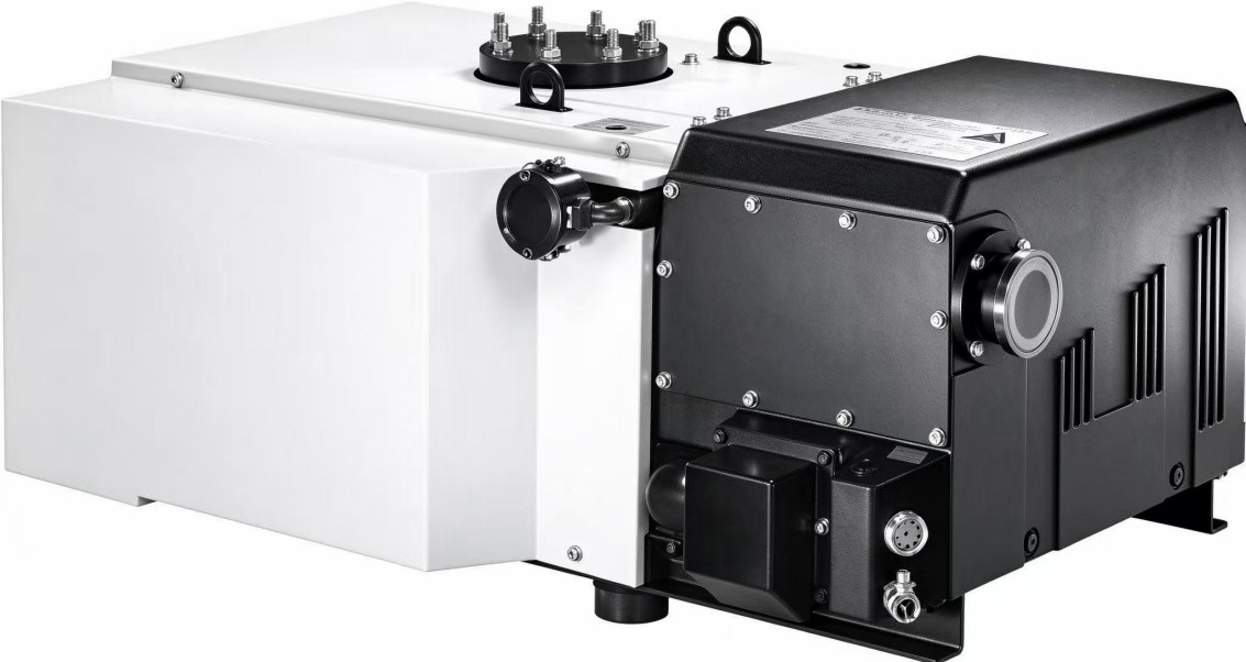
Most badly configured heat treatment pump sets are not undersized. They were simply never calculated for the section between the furnace flange and the pump inlet. A 4 m³ furnace with a 640 m³/h pump should reach 0.5 mbar in two or three minutes on paper; on site it takes seven or eight. The missing minutes are not in the pump — they are in a few metres of pipe and two flanges.
This article works through the calculation: the series formula first, then a full worked example for a heat treatment furnace pump set covering speed, bore and pump-down time, then the Roots stage at deep vacuum, and finally a leak-rate check using pressure rise rate.
1. A pump set is not two pumps bolted together
Between pump and chamber there is always piping, valves and a filter. Each element has a conductance C, in the same unit as pumping speed. In series they do not add — the reciprocals add:
1 / S_eff = 1 / S_pump + 1 / C_piping
This fixes a basic fact about heat treatment pump sets: when pipe conductance is lower than pump speed, a larger pump does not help, because effective speed is clamped by the conductance and cannot exceed it.
For a long circular tube in viscous flow — the rough vacuum range, Knudsen number below 0.01 — with air at 20 °C and η = 1.82×10⁻⁵ Pa·s:
C = π d⁴ p̄ / (128 η L)
with d the bore (m), L the length (m) and p̄ the mean pressure (Pa). Bore enters to the fourth power: halve the diameter and conductance falls to one sixteenth. That is why the same pump on DN100 and on DN50 produces curves more than a factor of two apart.
Elbows and tees have no closed form; in practice they are converted to equivalent straight length. This example folds 6 m of straight pipe into 10 m equivalent, which errs on the conservative side.
2. Worked example: 4 m³ furnace, DN100 piping, target 0.5 mbar
Duty: vacuum quench furnace, net chamber volume 4 m³, working pressure 0.5 mbar, main pump DPL-V630B (640 m³/h actual at 50 Hz, ultimate ≤8×10⁻² mbar with ballast closed, DN100/DN160 inlet).
Conductance for DN100 at 10 m equivalent length, against pressure:
| Mean pressure | Conductance C | Effective speed | Share of nameplate |
|---|---|---|---|
| 1 mbar | 4855 m³/h | 565 m³/h | 88% |
| 0.5 mbar | 2427 m³/h | 506 m³/h | 79% |
| 0.1 mbar | 485 m³/h | 276 m³/h | 43% |
The point often missed: in viscous flow, conductance is proportional to pressure, so the same pipe gets worse as the pressure drops. At 0.1 mbar this DN100 line passes only 43% of the pump’s speed.
Pump-down time, isothermal approximation, calculated in two stages:
t = (V / S) × ln(p₁ / p₂)
- 1013 → 10 mbar at a conservative 565 m³/h: t₁ = (4 / 565) × 3600 × ln(101.3) = 118 s, about 2.0 min
- 10 → 0.5 mbar at 550 m³/h: t₂ = (4 / 550) × 3600 × ln(20) = 78 s, about 1.3 min
Total about 196 s, or 3.3 min. Ignore piping altogether and the same 640 m³/h gives 172 s (2.9 min): piping accounts for roughly 14%, and the share grows as the target pressure falls.
Now replace DN100 with a DN50 reducer — common where the furnace port is G2″ and the pump inlet is DN100:
| Piping | Conductance at 0.5 mbar | Effective speed | Share of nameplate |
|---|---|---|---|
| DN100, L=10 m | 2427 m³/h | 506 m³/h | 79% |
| DN50, L=10 m | 152 m³/h | 123 m³/h | 19% |
The same DPL-V630B delivers only 123 m³/h at the chamber. Recalculated, the 10 to 0.5 mbar stage stretches from 78 s to 320 s (5.3 min) and the whole cycle from 3.3 to 7.3 min. This is the most common route to “the pump is fine but the cycle is not”: size the reducer to the pump flange, not to the furnace thread, and keep it short.
3. Worked example: 0.05 mbar, and why LC2600 delivers only a few hundred
Below 0.05 mbar a single-stage pump reaches its floor, so a two-stage pump plus a Roots stage is used. Take the pairing published on our own product pages: DPL-2V275 (255 m³/h, 7.5 kW, ultimate 5×10⁻⁴ mbar, ISO63 inlet) as backing, LC2600 (2600 m³/h, ISO160 inlet) as the booster.
At 0.05 mbar, over 10 m equivalent:
| Piping | Conductance C | Effective speed with a 2600 m³/h stage |
|---|---|---|
| DN100, L=10 m | 243 m³/h | 222 m³/h |
| DN160, L=10 m | 1591 m³/h | 987 m³/h |
A 2600 m³/h Roots pump on DN100 piping delivers 222 m³/h to the chamber. On DN160 the same pump delivers 987 m³/h — 4.4 times more. Sizing interstage piping to the backing pump instead of the Roots inlet is the single most expensive mistake in this pressure range.
The second limit is the backing pump. Roots rotors do not compress gas; they transfer it, so inlet throughput is capped roughly by backing speed multiplied by the compression ratio at that pressure. The 2V275 to LC2600 pairing is about 1:10 and is a typical published combination, so the backing pump is not the bottleneck here — the piping is. Hence the fixed order of checks: conductance first, then the speed ratio, then the pump itself.
Two control requirements belong in the logic: a Roots stage must never start against atmosphere, the inlet has to be pumped down to the permitted pressure first (the value is in the manual for each model); and shutdown runs in reverse — Roots first, backing pump second, otherwise the Roots exhaust is blocked while the backing pump stops. Differential-pressure interlock is not optional and should never be bypassed.
4. Leak check: what pressure rise rate costs in pumping speed
After sizing, convert the pressure rise rate into a gas load. For a 4 m³ chamber at the 0.67 Pa/h figure quoted from JB/T 8195.3 (some furnaces do better — the published DB-SAF644 vacuum furnace from the Wenzhou Pump and Valve Engineering Research Institute of Lanzhou University of Technology states ≤0.4 Pa/h, ≤6×10⁻³ Pa working pressure and ≤60 min pump-down):
Q = V × Δp / Δt = 4 × 0.67 = 2.68 Pa·m³/h = 7.44×10⁻⁴ Pa·m³/s, or 7.44×10⁻³ mbar·L/s.
- Holding that load at 1 mbar needs S = Q / p = 7.4×10⁻³ L/s, about 0.027 m³/h. A mechanical pump is far oversized for outgassing at this pressure.
- Holding the same load at 6×10⁻³ Pa needs S = 7.44×10⁻⁴ / 6×10⁻³ = 0.124 m³/s, about 446 m³/h — and that pressure is already outside the working range of a rotary vane pump.
The conclusion is blunt: in the mbar range, size the pump for volume and cycle time, not for outgassing. Outgassing only bites below 10⁻² Pa, and adding mechanical pump capacity is the wrong lever there.
5. Configurations for three typical furnaces
| Furnace | Net volume | Working pressure | Pump set | Note |
|---|---|---|---|---|
| Laboratory box or tube furnace | 0.3-0.8 m³ | 1 mbar class | DPL-V0155 single unit (150/175 m³/h, 4.0 kW, 0.3 mbar, G2″) | Direct pumping with an inlet filter; keep the line at G2″, do not reduce it |
| Medium tempering or annealing furnace | 1-2 m³ | 0.5 mbar | DPL-V0302 (300/360 m³/h, 7.5 kW) | Little margin; anything below DN100 adds minutes |
| Medium furnace, 0.1 mbar class | 1-2 m³ | 0.1 mbar | DPL-V300B (280 m³/h, 5.5 kW, ≤0.08 mbar) | Short body, easy to fit inside a packaged system |
| Large vacuum quench furnace | 3-6 m³ | 0.5 mbar | DPL-V630B (700 nominal / 640 actual m³/h, 15 kW, DN100/DN160) | Three-stage gas ballast; 730 kg, build the foundation for the weight |
| Large furnace with deep pumping | 5-10 m³ | below 0.05 mbar | DPL-2V275 + LC2600 (255 + 2600 m³/h) | Interstage piping at ISO160; DN100 cuts Roots speed by about 80% |
6. Five recurring mistakes
- Piping sized to the furnace thread. A G2″ port and a DN100 pump inlet connected by a reducer drops conductance at 0.5 mbar from 2427 to 152 m³/h. Match the bore to the pump flange and keep the reducer short.
- Cycle time calculated on nameplate speed. Nameplate is measured at the pump flange. Deduct piping, bends and filter before quoting a cycle time; the discount grows as pressure falls.
- Treating Roots as a speed multiplier for everything. Roots amplifies speed at one pressure point and does not change ultimate pressure. If the backing pump’s ultimate is not low enough, no Roots size helps.
- Interstage piping sized to the backing pump. That line sets the Roots back pressure; long and thin raises it, and temperature and motor load follow.
- Copying 50 Hz data to 60 Hz supplies. Speed and motor rating change with frequency, and some models are not suitable for 60 Hz regions. Confirm power supply and model before ordering for export.
Related reading
- Vacuum heat treatment furnace: pump configuration and speed calculation
- LC series Roots vacuum pumps LC250-LC4200
- DPL-V630B single-stage oil-sealed rotary vane pump
- Two-stage 2V80 / 2V275 oil-sealed rotary vane pumps
- Vacuum pumps for heat treatment and metallurgy
- Pumping speed and pump-down time calculator
Some models are not suitable for 60 Hz regions. Please confirm power supply and model compatibility before ordering for export projects.