
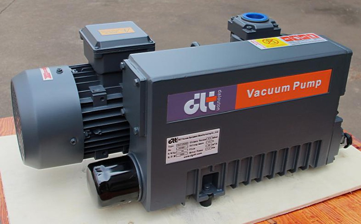
The same oil-sealed rotary vane pump holds 0.1 mbar on dry air, yet turns its oil milky within a quarter when the process gas carries 0.5 kg/h of water vapour. In vacuum pump selection the first branch point is not the pumping speed but the gas itself: condensable fractions condense into the oil, dust wears the clearance between vanes and chamber, and corrosive media attack the valves first and the chamber second. Each case calls for a different action — gas ballast, inlet filtration, or a different pump type — and each can be checked with a calculation before the order is placed.
1. Sort the gas into one of three groups
| Gas characteristic | What fails first | What to change in the selection |
|---|---|---|
| Condensable fraction (water vapour, solvent vapour) | Oil emulsifies, ultimate pressure drifts up, oil life drops from 2000 h to a few hundred hours | Gas ballast plus upstream condenser, checked at the exhaust side |
| Dust and particles | Vane wear, loss of chamber roundness, blocked oil passages | Inlet filter, then recalculate effective pumping speed |
| Acidic, halogenated, solvent-laden media | Corroded valves and chamber walls, failed seals | Upstream scrubber/condenser, or a dry-running pump with an oil-free chamber |
The hard case is the combination: water vapour plus acid means the condensate lands straight in the oil, so corrosion and emulsification arrive together.
2. Condensable vapour: calculate at the exhaust side, then decide on gas ballast
Most checks stop at the inlet pressure and conclude that 8 mbar is far from the saturation pressure of water. The vapour is not compressed to near atmosphere until it reaches the exhaust, and that is where condensation happens.
Three expressions are enough:
- Vapour volume flow V_w = (m / M) × R × T / p, with m in g/h, M = 18.015 g/mol, R = 8.314 J/(mol·K), T in kelvin, p the inlet absolute pressure in Pa.
- Partial pressure at the inlet p_w = p × (V_w / S), where S is the pump speed at that pressure.
- Partial pressure at the exhaust p_dis = p_w × K, with the compression ratio K ≈ p_exhaust / p_inlet, about 1013 mbar when discharging to atmosphere.
Worked example: chamber at 8 mbar and 40 °C, 0.5 kg/h of water vapour, DPL-V0100 (100 m³/h at 50 Hz, 3.0 kW, ultimate pressure 0.1 mbar with ballast closed and 0.5 mbar with ballast open).
- Molar flow: 500 g/h ÷ 18.015 g/mol = 27.75 mol/h
- Volume flow at 40 °C and 8 mbar: 27.75 × 8.314 × 313.15 ÷ 800 = 90.3 m³/h
- Share of pump capacity: 90.3 ÷ 100 = 90 %, so 7.2 mbar of the 8 mbar inlet pressure is water vapour
- Compression ratio: 1013 ÷ 8 ≈ 127, giving about 915 mbar of water vapour at the exhaust
- Saturation pressure of water at 70 °C is about 312 mbar (Antoine equation, consistent with IAPWS data), far below 915 mbar
So without gas ballast the vapour must condense in the oil. Running the same numbers backwards: with the ballast closed the inlet vapour partial pressure may not exceed 312 ÷ 127 ≈ 2.5 mbar, meaning vapour can be at most about 30 % of an 8 mbar inlet — the pump simply cannot serve this duty that way.
With the ballast open the compression ratio is diluted to roughly 10 (when to open the gas ballast valve covers the mechanism), so the allowable inlet vapour partial pressure rises to 312 ÷ 10 ≈ 31 mbar, four times our 7.2 mbar. The price is ultimate pressure, from 0.1 mbar to 0.5 mbar. Where the process needs better than 0.5 mbar, do not leave the ballast open permanently — put a condenser upstream. Ratings are on the V0025A–V0100 single-stage oil-sealed vane pump page.
3. Dust: convert filter pressure drop into effective pumping speed
The catalogue speed is measured at the pump inlet. A dust filter sits ahead of it, and its pressure drop combines with the pump in series and removes part of that speed:
- Filter conductance C = p × S ÷ Δp (p in mbar, S the pump speed at that pressure in m³/h, Δp the filter drop in mbar)
- Effective speed S_eff = 1 ÷ (1/S + 1/C)
Worked example: DPL-V0063 (63 m³/h at 50 Hz, 2.2 kW) at 100 mbar, new filter dropping 8 mbar at that flow.
- C = 100 × 63 ÷ 8 ≈ 787 m³/h
- S_eff = 1 ÷ (1/63 + 1/787) ≈ 58.3 m³/h, 7.4 % below the rating
Once dust bridges the media and the drop reaches 30 mbar:
- C = 100 × 63 ÷ 30 = 210 m³/h
- S_eff = 1 ÷ (1/63 + 1/210) ≈ 48.5 m³/h, 23 % below the rating
On the shop floor this becomes cycle time. Pumping a 2 m³ chamber from 1013 mbar to 100 mbar, estimated as t = (V / S_eff) × ln(p1 / p2) (isothermal, leaks and outgassing ignored, speed taken near 100 mbar):
- New filter: t = (2 ÷ 58.3) × ln(10.13) ≈ 0.079 h, about 283 s
- At 30 mbar drop: t = (2 ÷ 48.5) × ln(10.13) ≈ 0.099 h, about 355 s
That is 72 s per cycle — two hours of capacity per 100 cycles, before counting the speed loss from vane wear once dust gets through. A differential pressure gauge is not decoration; changing cartridges on its reading beats a fixed schedule. See inlet filtration and dusty duty for the configuration details.
4. Corrosive media: first ask whether they must enter the oil at all
With acids, chlorinated compounds or solvent vapour, the problem is not whether the pump can move the gas but that the oil is contaminated: acidic condensate emulsifies and acidifies it, valves and chamber walls begin to pit, and by the time the pressure drops it is already late. The order of treatment:
- Condense or scrub the condensable corrosive fraction upstream of the pump.
- For rough vacuum only (tens to hundreds of mbar absolute), use a dry-running claw pump with an oil-free chamber: DPL-ZS150 (140 m³/h, ultimate 60 mbar, 3.5 kW) and DPL-ZS300 (300 m³/h, ultimate 150 mbar, 6.8 kW) carry oil only in the timing-gear box.
- If both 0.1 mbar class pressure and corrosion resistance are required, materials, seals and upstream treatment must be confirmed case by case rather than taken from a standard model.
Note that ZS series ultimate pressure stops at 60 mbar and 150 mbar — they replace liquid-ring or reciprocating pumps in the rough vacuum stage, not a 0.1 mbar oil-sealed vane pump.
5. Six questions to settle before selecting
- Gas composition, with partial pressure or mass flow of each component (mol % or kg/h)
- Water vapour load (kg/h) and chamber temperature
- Dust particle size, concentration, stickiness and static charge
- Presence of acids, halogens or solvents
- Target pressure and allowed pump-down time
- Duty cycle and ambient temperature (above 40 °C the ratings must be recalculated)
Miss one of these and the selection becomes a guess. For 60 Hz regions, note that some models are not suited to 60 Hz supplies and the motor and speed configuration must be confirmed before ordering.