
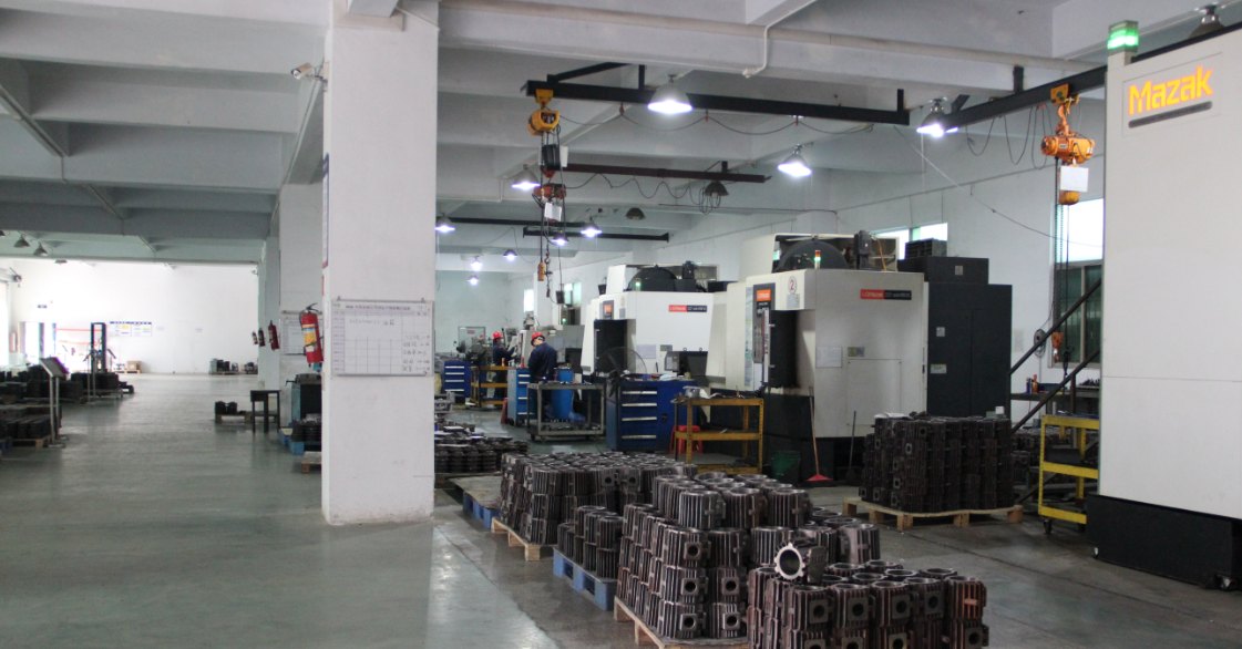
Vacuum tightness is not something you obtain by tightening bolts at assembly. From the same drawing, a pouring temperature off by tens of degrees, a skipped stress-relief cycle, or a seal face out of flatness by a few microns all end up as the same symptom: the pump stalls at a certain pressure, or pump-down takes longer than the reference unit. The pump body sits at the start of that chain — airtightness is fixed in casting and machining, and assembly only reveals it.
Separate the two figures: how fast, and how low
A leaking body shows up as two different problems with two different calculations.
Pump-down time follows t = (V / S) × ln(p0 / p1). For a DPL-2V18 rated at 17 m³/h (4.72 L/s), an 8 L chamber from 1013 mbar to 1 mbar takes t = (8 / 4.72) × ln(1013 / 1) ≈ 11.7 s. This figure depends on volume and pumping speed only; a small body leak barely changes the early part of the curve.
Ultimate pressure is different: p = Q / S, where Q is the total gas load entering the chamber (leakage plus outgassing plus process gas) and S is the effective pumping speed. The DPL-2V18 is rated at 1×10⁻³ mbar, which implies an allowable load of Q = 1×10⁻³ × 4.72 ≈ 4.7×10⁻³ mbar·L/s. Once the leak rate exceeds that line, no amount of pump quality gets you to the rated ultimate pressure.
Casting: porosity and shrinkage do not disappear during finishing
Pumps in production on our site are specified as cast iron / cast aluminium. Grey iron castings are accepted to GB/T 9439-2010 for tensile strength, hardness and microstructure; graphite morphology and matrix density govern machined surface quality and pressure resistance. Bodies with large wall-thickness steps tend to develop shrinkage porosity at the transition.
Dye penetrant testing (GB/T 18851.1) finds only defects open to the surface. Internal porosity, shrinkage and slag require X-ray or industrial CT; aluminium castings are commonly radiographed to GB/T 11346. The two classes are handled differently: surface-connected defects can be repaired, internal ones cannot.
Vacuum pressure impregnation is often treated as a cure-all. It seals connected porosity only — closed porosity, slag inclusions and cold shuts remain. Judge connectivity before impregnation and re-test the leak rate afterwards, otherwise the body still leaks under test. This is a frequent source of rework on the line.
Machining: flatness of the seal face matters more than roughness
The mating face between body and end cover decides whether the gasket or O-ring is compressed evenly. Flatness is evaluated to GB/T 1958-2017 by grid-point scanning on a CMM.
In industry inspection practice, flatness dominates sealing performance while roughness only affects micro-contact: gasket compression absorbs micro peaks, but not overall warpage. When flatness is out of tolerance, higher bolt preload cannot make the gasket deform uniformly, and local gaps become leak paths under vacuum.
Warpage usually starts as internal stress. If the casting is not stress-relieved after shakeout, or a thick-walled body gets only one cycle, rough machining removes a layer of metal and redistributes the stress; the finished seal face then creeps over the following weeks. Standard practice is one stress-relief cycle after casting and a second one after rough machining. Cast iron releases stress slowly; cast aluminium is more sensitive to machining stress, so the two cannot share one set of parameters.
Pressure-rise screening before assembly: a criterion you can calculate
The pressure-rise test measures pressure change with the valve closed: Q = V × (Δp / Δt), with V in litres, Δp in mbar and Δt in seconds, giving mbar·L/s. With large temperature swings, apply the correction Q = V × {[p2 × (T1 / T2)] − p1} / (t2 − t1), as published in the static pressure-rise method notes of the National Superabrasives Quality Inspection and Testing Center.
Worked example: an assembled body cavity of V = 8 L, valve closed for 300 s, pressure rising 0.40 mbar.
- Measured leak rate Q = 8 × 0.40 / 300 = 1.07×10⁻² mbar·L/s.
- For the DPL-2V18 the allowable figure is 4.7×10⁻³ mbar·L/s, so the measured value is 2.3 times the limit.
- Using p = Q / S, ultimate pressure would settle around 2.3×10⁻³ mbar instead of the rated 1×10⁻³ mbar.
Turned around, this gives a shop-floor criterion: for an 8 L cavity, pressure rise over 300 s must stay below Q_allow × Δt / V = 4.7×10⁻³ × 300 / 8 ≈ 0.18 mbar to pass.
The same criterion does not transfer to large pumps. The DPL-V630B at 640 m³/h (50 Hz) equals 177.8 L/s, with an ultimate pressure ≤8×10⁻² mbar, so the allowable load is 0.08 × 177.8 ≈ 14.2 mbar·L/s; over 8 L and 300 s that permits a 533 mbar rise, which has no screening value. Large bodies go straight to quantitative helium testing.
Distinguish leakage from outgassing as well. If the time needed for the same Δp grows cycle after cycle, outgassing is decaying; a constant Δt indicates a real leak. Drying, purging with dry gas and a cold trap ahead of the gauge all suppress the water-vapour background.
Helium testing: three to four orders of magnitude more sensitive
Pressure-rise sensitivity is roughly 10⁻⁴ to 10⁻⁶ Pa·m³/s; helium mass-spectrometer sniffing reaches about 1×10⁻⁸ Pa·m³/s and vacuum mode reaches the 10⁻¹² Pa·m³/s range. Specifications published by the Shanghai Institute of Optics and Fine Mechanics, CAS, list 5×10⁻¹³ Pa·m³/s in vacuum mode and 1×10⁻⁸ Pa·m³/s in sniffing mode.
One conversion to remember: 1 mbar·L/s = 0.1 Pa·m³/s. So 1×10⁻⁸ Pa·m³/s equals 1×10⁻⁷ mbar·L/s, two to three orders below routine pressure-rise sensitivity.
On methods, helium spray testing follows ISO 20486 and the accumulation method GB/T 32218-2015. Division of labour: pressure rise for post-assembly screening, cheap enough for 100 % inspection; helium testing for final release and disputes, with the measured value in Pa·m³/s or mbar·L/s written into the inspection record.
Five steps, none of them optional
Casting (density plus NDT) → stress relief → finish machining (seal-face flatness) → pre-assembly pressure rise (screening) → final helium test (quantitative release).
Any step skipped does not vanish; it returns as rework or a field complaint. On the user side, check pump-down time and pumping speed with the selection calculator, then follow the troubleshooting order in the FAQ to separate leakage, blockage and undersizing. Where lower ultimate pressure is required (coating, vacuum heat treatment), the tightness of the backing pump body decides whether the main pump ever reaches working pressure. Model data are on the DPL-2V18 and DPL-V630B pages; on the oil-free DPL-ZS150, a through-wall pore in the body connects the process side directly to atmosphere.