
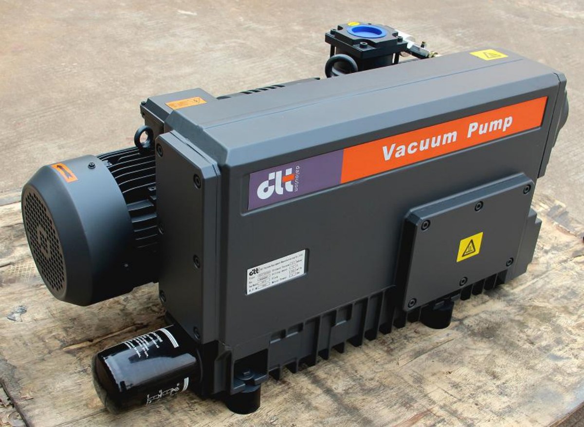
A pump that has lost pumping speed is often declared worn out before anyone measures anything, and the number of those pumps that turn out to be fine is not small: the gas is coming in somewhere else, or the speed never reaches the chamber. Work in the order of classify, measure, then dismantle, and the search narrows to one point in two or three hours.
1. Split the symptom in two
| Symptom | How to tell | What it points to |
|---|---|---|
| Ultimate pressure not reached | Stable pressure with the inlet valve closed is above the pump’s ultimate | Leak rate, condensable gas, oil condition, pump capability |
| Reaches target but slowly | Stable pressure normal, pump-down time longer than before | Effective pumping speed: piping, filter, local restriction, internal leakage |
Compare against the sample values first: V0025A to V0100 reach 0.1 mbar with gas ballast closed and 0.5 mbar with it open; V0160 to V0302 reach 0.1 mbar (0.5 mbar for V0250 and V0302); V630B reaches ≤8×10⁻² mbar; 2V80 reaches 4×10⁻⁴ mbar. If the system stalls at 0.08 mbar behind a V0160, calculate the gas load before blaming the pump.
2. Start with the pressure rise test, it costs the least
Isolate the chamber from the pump, close the inlet valve, and log pressure against time:
Q = ΔP × V / Δt
With a 2 m³ chamber rising from 0.02 to 0.17 mbar in 300 s, ΔP = 0.15 mbar and Q = 0.15 × 2 ÷ 300 × 1000 = 1 mbar·L/s.
Put that leak against the pump: 160 m³/h is 44.4 L/s, so the leak alone holds pressure at 1 ÷ 44.4 ≈ 0.023 mbar. The pump can reach 0.1 mbar, the system never gets below about 0.12 mbar, and no amount of adjustment changes it.
The same relation sets the leak-detection limit. A 2V80 (74 m³/h, about 20.6 L/s) held at 1×10⁻³ mbar tolerates only 1×10⁻³ × 20.6 ≈ 0.02 mbar·L/s, 48 times below the leak above. The pressure rise test cannot resolve that, so use the tracer gas method: ISO 20485:2017 defines the vacuum and pressure techniques, and GB/T 40335-2021 adopts it with modifications. Scan slowly, a fast sweep misses small leaks.
One caveat when reading the curve: the first section rises fast from wall desorption. Take the slope from the linear part, otherwise the “leak rate” is really a desorption rate.
3. Back-calculate effective pumping speed from the pump-down curve
t = (V / S) × ln(P0 / P1)
For the same 2 m³ chamber and a V0160 rated 160 m³/h, 1013 mbar to 10 mbar takes (2 ÷ 160) × 3600 × ln(101.3) ≈ 208 s.
On site the same step measured 210 s, which looks acceptable, except the measurement covered 100 mbar to 10 mbar, where theory gives 104 s. Feeding the measurement back:
S_eff = (V / Δt) × ln(P1 / P2) = (2 ÷ 210) × ln(10) ≈ 0.0219 m³/s ≈ 79 m³/h
Half of the rated speed. The pump turns and the pressure falls, but the chamber only sees 49 percent of the nominal figure, so the question becomes what is lost between pump inlet and chamber.
4. Pipe conductance: turn the loss into a number
1 / S_eff = 1 / S_p + 1 / C
With S_eff = 79 m³/h and S_p = 160 m³/h, C ≈ 156 m³/h (43 L/s).
Check that against the hardware. A DN50 line (50 mm bore), 4 m straight, two 90° elbows counted as 20 diameters each, gives 6 m equivalent length. For viscous flow in a long tube:
C ≈ (π d⁴ / 128 η L) × p̄, with η ≈ 1.8×10⁻⁵ Pa·s for air at 20 °C
At d = 0.05 m and L = 6 m: about 1.4×10⁴ L/s at 100 mbar, 1.4×10³ L/s at 10 mbar, 142 L/s at 1 mbar, and 14.2 L/s at 0.1 mbar. In molecular flow, C = 12.1 × d³ / L (d and L in cm, result in L/s) gives only 2.5 L/s for DN50 over 600 cm.
So near 10 mbar the pipe should pass thousands of m³/h while the measured equivalent conductance is 156 m³/h. That gap is not bore size, it is a local restriction: a ball valve not fully open, a loaded inlet filter, a hose collapsed under vacuum, a check valve stuck half open, or a bellows one size smaller than the pump inlet. V0160 has a G2″ inlet; reducing at the connection throws away the port.
The same arithmetic explains the common report that pumping slows below 1 mbar: at 0.1 mbar the DN50 line passes about 51 m³/h and molecular flow drops it to a couple of litres per second. Once the line is cleared, check the pump: oil level and grade, emulsified oil, blocked inlet filter, worn vanes and exhaust valves, a loaded oil mist separator that raises back pressure, a slipping coupling insert. Check speed as well: the same pump delivers different speed at 50 and 60 Hz (160 / 190 m³/h for V0160), and some models are not suited to 60 Hz areas, so confirm motor and speed configuration with the factory before changing frequency or exporting.
5. When pump and piping are both fine, look at the gas
With water vapour or solvent vapour the pump still moves gas, but condensable fractions accumulate in the oil; once the oil emulsifies, ultimate pressure and speed fall together. Gas ballast is the answer, and the cost is printed on the data sheet: 0.1 mbar becomes 0.5 mbar from V0025A to V0100, and V630B moves from ≤8×10⁻² mbar to ≤0.7 mbar. That is by design, not a fault. Judge these duties by pump-down time and oil condition instead of ultimate pressure.
6. The order in one list
- Record the baseline: chamber volume, target pressure, pump-down time, stable pressure, oil grade and running hours.
- Pressure rise test, compare with the allowed leak rate, then locate with tracer gas if it fails.
- Back-calculate effective pumping speed from the pump-down curve.
- Back-calculate equivalent conductance and compare it with the calculated pipe conductance.
- Check valve position, filter element, hose, check valve.
- Check the pump: oil, filter, vanes, exhaust back pressure.
- Re-check the sizing last, using the pump-down calculator with chamber volume and target time.
Every step above produces a number, which is the point: “the pump is weak” becomes “the leak is this much, the conductance is this much, the pump still delivers this much”. Compare with the published figures for the V0160–V0302 single-stage oil-sealed vane pumps and the 2V80 / 2V275 two-stage pumps, and check the selection criteria in the FAQ.