
On a coating floor three chambers often share one pump set in a pump room some distance away. Load, evacuate, coat, vent, unload. The number operators watch is cycle time: the early shift pulls a chamber from atmosphere to the hand-over pressure in six minutes, and by the afternoon the same chamber takes eight and a half. Nothing on the chamber changed and no pump has failed, yet the timing will not hold.
This drift is rarely a broken pump. More often the pumping speed is dropping out mid-range. The points below come up repeatedly.
1. Roughing runs in two stages, and each stage needs something different
A coating chamber passes through two pressure regions between atmosphere and process vacuum. From atmosphere down to tens of millibar the gas load is large and the backing pump moves it. Below that a booster takes over and pushes lower, while the high-vacuum stage belongs to a turbomolecular or diffusion pump. An undersized backing pump slows the front half; a badly matched booster drags the back half.
Single-stage oil-sealed rotary vane pumps are the usual choice. The V0155 is rated 150 m³/h at 50 Hz with a 4.0 kW motor and 0.3 mbar ultimate vacuum with the gas ballast closed, G2" inlet and exhaust. Above it the V0160 gives 160 m³/h at 4 kW and 0.1 mbar; the V0202 gives 200 m³/h at 5.5 kW, also 0.1 mbar; larger chambers take the V0302 at 300 m³/h and 7.5 kW. Where space is tight and around 280 m³/h is enough, the V300B offers 5.5 kW, 0.08 mbar and a 1100 mm body. In continuous duty this range runs below -300 mbar gauge at 0 to 35 °C.
2. A booster’s speed depends on inlet pressure, not on the nameplate
The LC series is rated 250, 500, 1200, 2600 and 4200 m³/h at 50 Hz, with 2.2, 2.2, 4.0, 7.5 and 11 kW motors and inlet flanges from ISO63 to ISO250. Those figures hold at high enough inlet pressure. As pressure falls, the volume a Roots stage can carry falls with it, and effective speed increasingly depends on what the backing pump still delivers at that same pressure point.
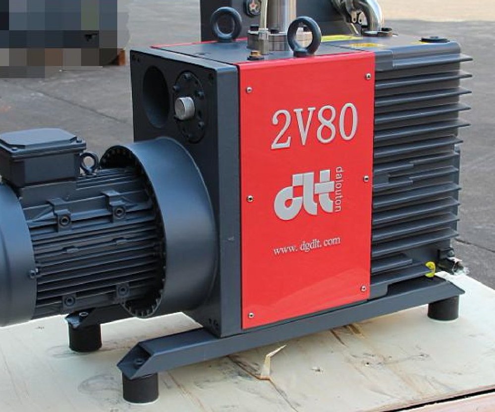
The order is: fix the working pressure, choose the booster for the speed required at that pressure, then check the backing pump at the same point. Comparing two nameplate numbers produces combinations that look adequate and are not. Typical pairs are the 2V80 with the LC250 and the 2V275 with the LC2600, used for coating, vacuum heat treatment and roughing of large chambers.
3. Differential pressure and start sequence decide stability
Roots rotors do not touch the casing; sealing is by clearance, so an excessive pressure difference loads the motor. Start the backing pump first to establish a base vacuum, then bring the booster in, and build a pressure interlock into the control logic so the booster stays off below the set inlet pressure. Where the ratio is large, limit the differential with a relief valve or bypass.
Coating lines vent and restart often; with a loose interlock the booster is simply started at different inlet pressures, and behaves differently.
4. Piping and shared stations amplify the swing
The run between pump and chamber is often the bottleneck. Undersize pipe, too many bends, reduced-port valves: loss climbs steeply, and the symptom is slow evacuation and vacuum that will not come down. Keep the bore no smaller than the pump port, go one size up on long runs, and keep valve bore no smaller than its line.
When several chambers share a pump set, fit a check valve on each branch so venting one chamber does not drag the others down. Connect high-demand stations separately, or add a vacuum vessel at the end of a long run to absorb peaks instead of asking the pump to chase them. Joints and hoses are where leaks concentrate, so check the line before the pump.
5. Water vapour and oil affect stability, not peak performance
The roughing stage usually carries some water vapour and process residue. Open the gas ballast for condensable gas; ultimate vacuum falls back to the 0.5 mbar range; that is normal. When the process needs the ultimate figure, close the ballast and fit a cold trap on the inlet side. Dust-laden gas needs an inlet filter, and an oil mist separator belongs on the exhaust.
Oil charge is set per model: 4 L for the V0155, 6 L each for the V0160 and V0202, 8 L for the V0302 and 8.5 L for the V300B. Change the oil when it emulsifies or darkens and clean the mist separator element at the same time; dust and moisture shorten the interval.
Selection and upkeep
Work back from chamber volume, hand-over pressure and cycle time to the effective speed, and include line losses. Keep the speed ratio between booster and backing pump within a sensible band, and add a bypass where the ratio is large. Three daily checks cover most problems: oil level and colour, differential across the inlet filter, and inlet pressure when the booster cuts in. If cycle time stretches, check filter and line before the pump.
Send us the chamber volume, target pressure and cycle time, and we will propose a pump combination with matching speeds.