
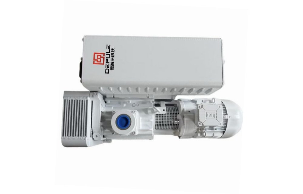
Throughput and film consistency on a coating line are decided to a large extent in the pumping stage. The same chamber with the same load takes six minutes to reach the handover pressure on the morning shift and eight and a half on the afternoon shift. Nothing was changed and no alarm was raised, yet the cycle will not hold. In most cases the pump is not broken: the effective pumping speed has dropped in the middle of the pressure range.
A PVD vacuum system is sensitive to pumping-speed fluctuation because three things depend on it at once: cycle time (one extra minute of roughing is one extra minute per batch), base pressure (if the chamber is not low enough before the process starts, adhesion and uniformity drift), and process pressure (sputtering runs at a working pressure in the 10⁻³ to 10⁻² mbar range, held by a throttle valve and a mass flow controller; if the backing side is weak, no amount of throttling recovers it). Sizing therefore needs four steps: duty checklist, roughing calculation, process-gas calculation, pump set configuration.
1. Build the duty checklist first
Coating lines all look like “pump to high vacuum” until the details are written down. Fill in the eight items below before looking at any model; leave two blank and the configuration is a guess.
| Item | What to record | Why it drives pumping speed |
|---|---|---|
| Chamber volume | Net empty volume including fixtures and work | Pump-down time scales with volume |
| Allowed roughing time | Seconds from atmosphere to handover pressure | Sets the minimum effective pumping speed |
| Handover pressure | Pressure at which the backing pump hands over | Commonly in the 5-20 mbar range |
| Process working pressure | Pressure and gas type held during sputtering | Defines the process-gas load |
| Process gas flow | sccm of argon or other working gas | Converts directly into a throughput figure |
| Pumped media | Dust, moisture, solvent vapour, target volatiles | Decides filtration, condensation and gas ballast |
| Diversity factor | How many chambers share one pump set | Shared pumps split the available speed at peaks |
| Piping | Distance, bore, bends and valves from pump room to chamber | The largest hidden discount on effective speed |
2. Roughing: calculate the pump-down time
In the rough vacuum range, use the isothermal approximation t = (V / S) × ln(p₁ / p₂), where V is chamber volume, S the effective pumping speed and p₁, p₂ the start and target pressures. From 1013 mbar to 10 mbar, ln(1013/10) is about 4.62.
| Chamber volume | Pump | Rated speed | Ideal time | At 70% effective speed |
|---|---|---|---|---|
| 0.5 m³ | DPL-V0155 | 150 m³/h | 55 s | 79 s |
| 1.0 m³ | DPL-V0202 | 200 m³/h | 83 s | 119 s |
| 2.0 m³ | DPL-V0302 | 300 m³/h | 111 s | 158 s |
| 2.5 m³ | DPL-V300B | 240 m³/h actual | 173 s | 247 s |
| 3.0 m³ | DPL-V630B | 640 m³/h actual | 78 s | 111 s |
The second time column is the one to quote for cycle planning. The 70% factor is a coarse allowance for piping and valves; small bore, long runs and many bends push it lower still. This is not measurement error but the most frequently ignored loss in a vacuum system: the speed measured at the chamber and the speed measured after fifteen metres of pipe can differ by half.
Two further effects flatten the curve: outgassing from walls and fixtures, and leakage at seals and flanges. Neither scales linearly with pressure, and both become visible as the target pressure is approached. This is also why gas ballast is normally opened during roughing: it admits dry air and lowers the partial pressure of condensable components so that water vapour leaves with the mixture instead of condensing in the oil. The cost is a higher ultimate pressure, so the ballast is closed again before pulling down to the handover point.
3. Process stage: gas load sets the floor for the backing pump
Roughing moves air; sputtering moves process gas. The relation is Q = p × S. One sccm is roughly 1.27 × 10⁻² mbar·L/s, so 200 sccm of argon is about 2.54 mbar·L/s. Spread over different backing pressures:
| Backing pressure | Speed required for 200 sccm |
|---|---|
| 0.5 mbar | 18.3 m³/h |
| 0.3 mbar | 30.5 m³/h |
| 0.1 mbar | 91.4 m³/h |
| 0.05 mbar | 182.9 m³/h |
The conclusion is blunt: the lower the backing pressure, the harder the backing pump works. The same 200 sccm needs about 20 m³/h at 0.5 mbar and more than 180 m³/h at 0.05 mbar. Backing pump size cannot be discussed apart from the pressure at which it runs, which is why one model is sufficient on one line and marginal on the next.
4. Roots stage: nameplate speed only holds at high inlet pressure
Above roughly 1.5 m³, or when the cycle is tight, a mechanical pump alone is not enough and a Roots set is used. The usual mistake is treating Roots speed as a constant.
The LC series covers 250, 500, 1200, 2600 and 4200 m³/h at 50 Hz, with motor ratings of 2.2, 2.2, 4.0, 7.5 and 11 kW and inlet flanges from ISO63 to ISO250. Those figures hold when inlet pressure is high enough. As inlet pressure falls, the volume a Roots pump can move falls with it, and actual speed increasingly depends on what the backing pump still delivers at the same point. Typical pairings are 2V80 (74 m³/h, 3 kW) with LC250, and 2V275 (255 m³/h, 7.5 kW) with LC2600, for coating chamber roughing and large chamber evacuation.
Roots rotors do not touch and seal on clearance, so excessive differential pressure overloads the motor. On WSU2000, maximum permissible differential pressure is 50 mbar with 2050 m³/h, 7.5 kW and DN160 ISO-K flanges; that 50 mbar is the interlock boundary. Start the backing pump first, bring the inlet to the set pressure, then start the Roots stage, and limit differential pressure with a bypass or overflow valve rather than letting the backing pump absorb it.
5. Configuration by chamber volume
| Chamber volume | Handover | Pump | Motor | Ultimate (ballast closed) | Upgrade |
|---|---|---|---|---|---|
| 0.3-0.6 m³ | 10 mbar | DPL-V0155 (150 m³/h) | 4.0 kW | 0.3 mbar | LC250 for tight cycles |
| 0.6-1.2 m³ | 10 mbar | DPL-V0202 (200 m³/h) | 5.5 kW | 0.1 mbar | LC500 |
| 1.2-2.0 m³ | 10 mbar | DPL-V0302 (300 m³/h) | 7.5 kW | 0.5 mbar | LC500 / LC1200 |
| 2.0-3.0 m³, tight footprint | 10 mbar | DPL-V300B (280 nominal / 240 actual m³/h) | 5.5 kW | ≤0.08 mbar | LC500 |
| Above 3.0 m³ or fast cycle | 10 mbar | DPL-V630B (700 nominal / 640 actual m³/h) | 15 kW | ≤0.08 mbar | LC1200 or larger |
| Base pressure below 10⁻² mbar | — | DPL-2V80 / 2V275 with Roots | 3 / 7.5 kW | 4×10⁻⁴ / 5×10⁻⁴ mbar | Recheck backing speed at the backing pressure |
For V300B and V630B both nominal and actual speeds are listed: calculate cycle time on the actual figure. Nominal speed is geometric displacement, actual speed is measured, and the 8-9% difference is exactly what decides the seconds in the pump-down table.
6. Common pitfalls
- Comparing nameplate speed without fixing the working pressure. Two pumps 20% apart on the plate can differ twofold in actual speed at 0.05 mbar, because the curve is falling in that range.
- Piping sized to the pump flange instead of to the flow. A G2" inlet does not mean a G2" line: bends, bellows and valves each have to be checked. Piping loss is the only factor that lengthens the cycle without changing the pump.
- Sizing a shared pump set for a single chamber. Shared sets need the peak sum times the diversity factor; they save hardware but pass pressure excursions to every chamber.
- Leaving gas ballast open all day. It suppresses condensables at the cost of ultimate pressure and higher oil temperature. Close it before pulling down to the handover pressure.
- Ignoring oil condition. Pumping speed on an oil-sealed pump follows oil state: emulsified oil, low level or high temperature all reduce speed, and this is the most common physical reason a line is fast in the morning and slow in the afternoon.
- Copying 50 Hz data to 60 Hz supplies. Speed and motor ratings change with frequency. Some models are not suitable for 60 Hz regions; confirm before ordering for export projects.