
A rotary vane pump has three clearances that all get called “the clearance”, and they do different jobs. The side clearance between vane and rotor slot decides whether the vane can slide out freely or jams; the tip clearance between vane head and cylinder bore, and the end clearance between rotor/vane faces and end plates, are the actual paths for gas leaking back from the compression side. Blaming every loss of pumping speed on clearance is inaccurate: at 500 mbar a single 40 µm end clearance takes only about one percent of the pumping speed, while below 1 mbar the same gap can lift the ultimate pressure by an order of magnitude. This article separates the three clearances and uses three worked examples to show which pressure range each one governs — and why every wear problem eventually shows up as a larger gap.
1. Three clearances: position, order of magnitude, consequence
| Clearance | Position | Typical cold value | Main consequence |
|---|---|---|---|
| Side | Vane faces against rotor slot | 0.02–0.08 mm | Vane tilt, impact noise, slot-base leakage; excessive play causes vane rocking and edge wear |
| Tip | Vane head against cylinder bore | Tens of micrometres | Tip leakage; after wear it shows directly as higher ultimate pressure |
| End | Rotor and vane faces to end plate | 10–30 µm | Main end-face leakage path; oil-sealed pumps seal it with an oil film, dry pumps rely on geometry |
These are reference ranges for common machines, not drawing values for any specific pump. Real values must be measured, and measured hot — see section 4.
2. Example 1: clearance volume sets the 90–100 mbar ceiling of single-stage dry pumps
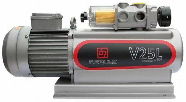
Single-stage oil-free vane pumps are rated at 90–150 mbar: the DPL-V15L and DPL-V25L at 90 mbar, the DPL-V8, DPL-V10 and DPL-V16 at 100 mbar. That figure is often blamed on poor clearances, but the dominant term is clearance volume: at the end of discharge, gas trapped in the residual volume at one atmosphere re-expands as the rotor turns, and suction only begins once it has dropped below inlet pressure.
For isothermal expansion, ultimate pressure follows:
p_u = p_exh × V_c / (V_c + V_cyc)
With p_exh = 1013 mbar, V_c the clearance volume and V_cyc the swept volume per revolution, the implied ratios are:
| Model | Rated vacuum | Implied V_c / V_cyc |
|---|---|---|
| DPL-V8 / V10 / V16 | 100 mbar | 100 ÷ (1013 − 100) = 11.0% |
| DPL-V15L / V25L | 90 mbar | 90 ÷ (1013 − 90) = 9.8% |
| DPL-V25 / V40 | 150 mbar (850 mbar gauge) | 150 ÷ (1013 − 150) = 17.4% |
The 10–17% band matches the geometry of a vane pump: the discharge port and the volume near top dead centre account for that order. It also means going deeper with a single dry stage is a question of shrinking the residual volume or adding a second stage, not of grinding another 5 µm off the gap.
Applied to an oil-sealed single stage the same model gives an absurd answer: the V0040A to V0100 are rated 0.1 mbar (V0025A–V0100 product page), which would imply a clearance ratio of 0.01% — not buildable. The reason is that the oil film fills the gap, part of the compressed gas dissolves in the oil, and the discharge valve dead volume can be made small. The 0.1 mbar of an oil-sealed pump does not come from geometry alone.
3. Example 2: one gap, two very different weightings
Treat the end clearance as a narrow slit and estimate its viscous conductance as:
C = b · h³ / (12 η L) Q = C · (p₂² − p₁²) / 2 ΔS = Q / p₁
with b the sealing width (45 mm), L the sealing length in the direction of rotation (45 mm), h the end clearance, η = 1.85×10⁻⁵ Pa·s for air at 20 °C, and p₂ = 1013 mbar. Two vanes with two end faces each give four parallel paths.
At 500 mbar (p₁ = 50 000 Pa), h = 40 µm gives about 0.08 m³/h per path, 0.32 m³/h for four, i.e. 1.3% of the 25 m³/h of a V25L. At h = 10 µm the figure is 0.02% — unmeasurable in the field.
Near ultimate pressure (p₁ → 0, p₂ still one atmosphere) the pV leak flux stops varying with p₁, and dividing it by the pump’s speed gives the ultimate pressure the gap allows:
| End clearance h | Leak per path | 25 m³/h pump, 4 paths | 100 m³/h pump, 4 paths |
|---|---|---|---|
| 10 µm | 0.023 Pa·m³/s | 0.13 mbar | 0.03 mbar |
| 20 µm | 0.19 Pa·m³/s | 1.1 mbar | 0.27 mbar |
| 40 µm | 1.5 Pa·m³/s | 8.5 mbar | 2.1 mbar |
| 60 µm | 5.0 Pa·m³/s | 29 mbar | 7.2 mbar |
This table explains a common failure report: an oil-sealed single stage rated 0.1 mbar, a few years in service, sits at 1–2 mbar no matter what — new oil, checked piping, still the same. At 40 µm end clearance that is exactly what the arithmetic allows. Note the cube: 10 to 20 µm multiplies conductance by 8, and 20 to 40 µm by another 8.
One boundary note: at 500 mbar the mean free path is about 0.13 µm, so the Knudsen number against a 10 µm gap is roughly 0.013 — near the lower edge of viscous flow and the formula applies. Below a few mbar the flow becomes transitional and then molecular, conductance no longer depends on pressure, and the leak flux levels off. That is why worn clearances hurt ultimate pressure first and roughing speed almost not at all.
4. Example 3: thermal expansion redistributes the cold gap
The assembly clearance is not the running clearance. Take a 100 mm cast iron rotor (α = 11.5×10⁻⁶/K, 50 K rise) and an aluminium housing and end plate of the same length (α = 23.5×10⁻⁶/K, 35 K rise):
- Rotor growth: 100 mm × 11.5×10⁻⁶ × 50 = 57.5 µm
- Housing growth: 100 mm × 23.5×10⁻⁶ × 35 = 82.3 µm
- End clearance change: 82.3 − 57.5 = +24.8 µm
Aluminium grows more than iron, so the hot end clearance is about 25 µm larger than cold; with h³ dependence, hot leakage is roughly three times the cold value. Tip clearance moves the same way: an 80 mm cast iron bore grows 36.8 µm at a 40 K rise, while a graphite or resin vane (α about 4×10⁻⁶/K) grows only 19.2 µm at a 60 K rise, adding 8.8 µm per side — a 20 µm cold tip clearance becomes 28.8 µm hot.
Two practical consequences: a small cold gap is not automatically better, because starting torque and dry-friction risk rise; and a pump should be judged on gap and ultimate pressure measured after two hours at operating temperature, not on the assembly sheet.
5. Service life: how clearance growth becomes a speed loss
Wear is gradual, and what can be measured comes in three stages: ultimate pressure rises first (leakage through tip and end clearance matters most at low pressure), medium-vacuum pumping speed falls next, and noise and vibration deteriorate last. From the table above, an end clearance growing from 10 to 40 µm moves the ultimate pressure from the 0.03 mbar class to the 2.1 mbar class, while the same wear costs only a few percent of pumping speed in the medium-vacuum range — so “speed still looks fine” is not evidence that the clearance is fine.
The five measurable signals for a vane change are covered in how to judge vane wear, and the measurement-first troubleshooting order in pumping speed loss. One addition: in dusty duty, tip clearance wears faster, and good inlet filtration changes vane life more than oil change intervals do.
6. Oil-sealed versus oil-free: what the oil film does for the gap
In an oil-sealed pump the oil film takes over the end clearance: it fills the micrometre-scale gap and drops the viscous conductance by orders of magnitude, which is how a single-stage oil-sealed pump reaches 0.1 mbar and a two-stage DPL-2V18 reaches 1×10⁻³ mbar. An oil-free pump has no such film; end and tip clearance rely on geometry and on the self-lubricating vane material, which is why it sits at 90–150 mbar and is more sensitive to dust and dry friction. Tolerances are not transferable: an end clearance acceptable in an oil-sealed pump would eat the whole low-pressure range of a dry pump, and a dry-pump tolerance in an oil-sealed pump would starve the oil film and score the faces.
7. Three rules for the plant floor
- Record the three cold clearances after an overhaul, then re-measure after two hours of running; judge on the hot values.
- Do not “compensate” wear with a thicker gasket: a gasket changes both clearance volume and vane protrusion, so speed and ultimate pressure move together. Re-grind the end face against the calculated thermal growth instead.
- When speed falls, measure effective pumping speed before opening the pump, and rule out inlet filtration and pipe conductance first.
For 60 Hz markets, confirm with the factory before ordering: higher speed means higher running temperature, so hot end and tip clearances differ from 50 Hz, and oil temperature rises in oil-sealed units. The datasheet notes that some models are not suitable for 60 Hz areas.