
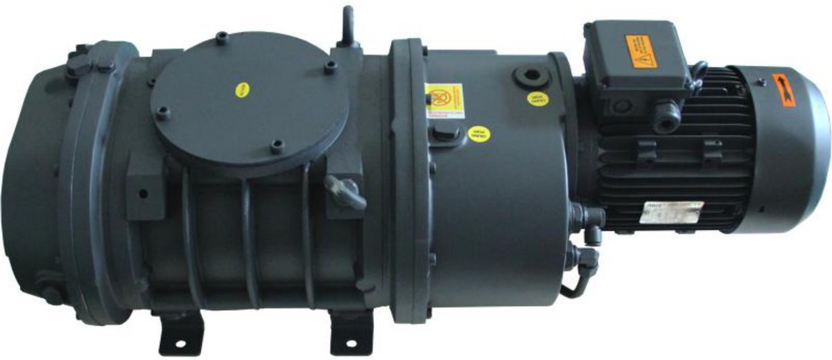
A Roots blower does not compress gas itself; it moves gas from the low side to the high side, and how much it can move depends on how much the backing pump can discharge. Half the sizing work in a Roots set is the backing pump match.
Two ratios, often confused. Speed ratio is Roots speed divided by backing speed — the number you choose at the desk. Compression ratio is exhaust pressure divided by inlet pressure — the number you read in service. They converge in steady operation, but compression ratio also moves with gas temperature, internal leakage and differential pressure. Size on the speed ratio, check against measured compression.
LC series basics.
| Model | Speed 50/60 Hz | Power | Inlet | Outlet | Weight |
|---|---|---|---|---|---|
| LC250 | 250 / 300 m³/h | 2.2 kW | ISO63 | ISO40 | 61 kg |
| LC500 | 500 / 600 m³/h | 2.2 kW | ISO100 | ISO63 | 69 kg |
| LC1200 | 1200 / 1440 m³/h | 4.0 kW | ISO160 | ISO100 | 149 kg |
| LC2600 | 2600 / 3120 m³/h | 7.5 kW | ISO160 | ISO100 | 308 kg |
| LC4200 | 4200 / 5040 m³/h | 11 kW | ISO250 | ISO100 | 400 kg |
Motor power does not scale linearly with speed: LC1200 to LC2600 more than doubles speed while power goes from 4.0 to 7.5 kW, because a Roots blower’s power goes into differential pressure, not throughput.
Choosing the ratio. Practice puts the speed ratio at 2–4. Two to three suits most continuous processes where differential pressure stays modest and temperature is controllable. Three to four is used when the process wants higher speed and the backing pump is limited by space or budget, and it demands attention to differential pressure and temperature. Above four, differential pressure grows enough that rotor thermal expansion can close the clearance against the casing — acceptable only for short evacuation cycles.
| Roots | Ratio | Backing | Note |
|---|---|---|---|
| LC1200 (1200 m³/h) | 1.9 | V0630B (630 m³/h) | low differential, continuous duty |
| LC2600 (2600 m³/h) | 4.1 | V0630B (630 m³/h) | near the limit, intermittent only |
Where the ceiling comes from. Roots rotors run non-contact and seal on clearance. The higher the compression ratio, the larger the share of gas leaking back through that clearance and the more actual speed falls away. Differential pressure also heats the gas, the rotors expand, and clearance shrinks. The maker’s allowable differential pressure is a hard limit: work out the worst case the process can produce, keep 30% in hand, and do not size against the ceiling.
Evacuation time is a two-stage calculation. The backing pump pulls down to the range where the blower can cut in, usually 10–30 mbar, then the blower starts. For a 1000 L chamber to 0.5 mbar with a 630 m³/h backing pump, a 20 mbar switch point and a 2600 m³/h blower: t₁ = (1 / 0.175) × ln(1013 / 20) ≈ 22 s, t₂ = (1 / 0.722) × ln(20 / 0.5) ≈ 5.1 s, so about 27 s before line losses and valve action — plan on 35–40 s.
What we need. Chamber volume, target pressure and allowable pump-down time, process outgassing, whether the gas is dusty or corrosive, supply and footprint.