
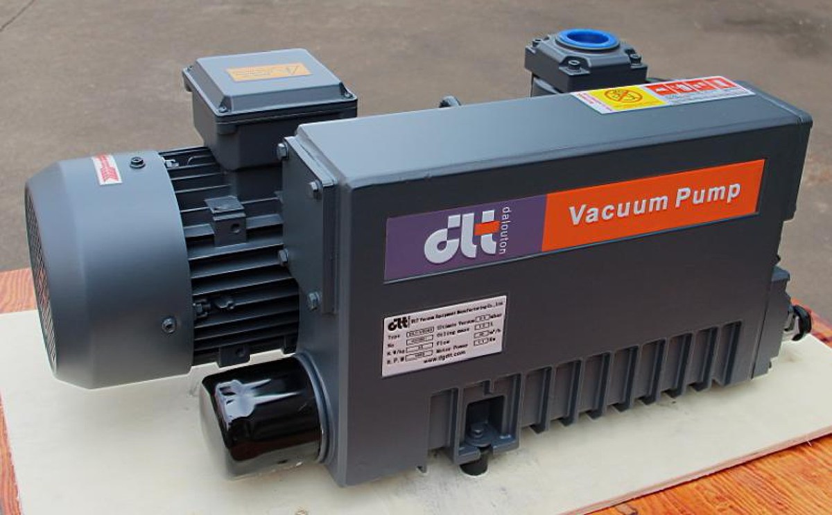
The most common misreading in a sizing meeting is treating ultimate pressure as “how low this pump will pull the chamber”. The difference between ultimate pressure and working pressure is simple: one figure is measured at the pump inlet with the inlet closed and no load, the other is measured inside a vessel that leaks, outgasses and carries process gas. The same V0100 is listed at 0.1 mbar, yet connected to a chamber through three metres of pipe, two bends and a slightly weeping flange, it may hold 0.4 to 0.5 mbar, and higher once process gas is admitted. The pump is fine; the arithmetic was wrong.
1. The two numbers are measured under different conditions
Ultimate pressure is the value reached with the pump correctly oiled, gas ballast closed and the inlet blanked off, running until the oil temperature is stable and the inlet pressure stops falling. The measuring point is the pump flange: no pipe, no vessel, no gas load.
Working pressure is the pressure to be held inside the chamber. It is set by the process and stands on four gas sources: leakage, outgassing from walls and workpieces, evaporation of condensables, and process gas fed in deliberately. The pump carries the sum of those four away. If it can, pressure holds; if it cannot, pressure drifts up.
The two columns in a datasheet are exactly these two states:
| Model | Rated speed (50 Hz) | Ultimate, ballast closed | Ultimate, ballast open |
|---|---|---|---|
| V0025A | 20 m³/h | 0.5 mbar | — |
| V0040A | 40 m³/h | 0.1 mbar | 0.5 mbar |
| V0063 | 63 m³/h | 0.1 mbar | 0.5 mbar |
| V0100 | 100 m³/h | 0.1 mbar | 0.5 mbar |
| V0155 | 150 m³/h | 0.3 mbar | 0.5 mbar |
| V0160 / V0202 | 160 / 200 m³/h | 0.1 mbar | — |
| DPL-V300B | 280 m³/h (about 240 actual) | ≤0.08 mbar | ≤0.7 mbar |
| DPL-V630B | 700 m³/h (about 640 actual) | ≤0.08 mbar | ≤0.7 mbar |
| 2V80 / 2V275 | 74 / 255 m³/h | 4×10⁻⁴ / 5×10⁻⁴ mbar | 5×10⁻³ mbar |
On one model the ballast column differs by a factor of five. It is not an option list; it is two different states of the same machine.
2. What is left of the pumping speed at the working pressure
Before the discharge valve opens, residual pressure on the outlet side pushes some gas back, so net speed tends to zero as inlet pressure approaches ultimate pressure. The usual engineering approximation:
S_eff = S × (1 − p_u / p)
with S the rated speed, p_u the ultimate pressure and p the working pressure. Applied to three current models:
| Working pressure | V0100 (100, p_u=0.1) | V0155 (150, p_u=0.3) | 2V80 (74, p_u=4×10⁻⁴) |
|---|---|---|---|
| 10 mbar | 99 m³/h | 135 m³/h | 74 m³/h |
| 1 mbar | 90 m³/h | 105 m³/h | 74 m³/h |
| 0.5 mbar | 80 m³/h | 60 m³/h | 74 m³/h |
| 0.4 mbar | 75 m³/h | 37.5 m³/h | 74 m³/h |
| 0.2 mbar | 50 m³/h | out of range | 74 m³/h |
| 0.01 mbar | out of range | out of range | 71 m³/h |
At 0.4 mbar the V0155 keeps 37.5 m³/h, a quarter of its rated figure. It does reach 0.4 mbar, but the speed at which it works there is no longer the number on the selection table. The two-stage 2V80, with an ultimate pressure three orders lower, barely loses speed anywhere in the medium vacuum range. That is what the extra stage buys.
The rule of thumb: when the working pressure is less than three to five times the ultimate pressure, recalculate the speed at the working point instead of quoting the rated value for cycle planning.
3. Open the gas ballast and the ultimate column changes
When the load carries water vapour or solvent vapour, gas ballast must be open: dry air is admitted to lower the partial pressure of condensables so they leave with the mixture instead of condensing in the oil. The price is in the table: V0040A goes from 0.1 mbar to 0.5 mbar.
The price goes beyond the ultimate value. For a process holding 1 mbar with ballast open all shift:
S_eff = 40 × (1 − 0.5 / 1) = 20 m³/h
Half the rated speed. Planning the cycle on 40 m³/h would understate the pump-down time by a factor of two. Wherever ballast must stay open, size on the ballast-open column and recalculate at the working point with it.
4. The second discount sits in the piping
Between pump flange and chamber there are pipes, valves, bellows and cold traps. They combine in series:
1 / S_eff = 1 / S_pump + 1 / C
with C the conductance of the line. For a V0155:
| Line conductance C | Effective speed at the chamber |
|---|---|
| 300 m³/h | 100 m³/h |
| 150 m³/h | 75 m³/h |
| 75 m³/h | 50 m³/h |
Measuring 150 m³/h at the pump and 75 m³/h at the chamber is an ordinary result. This loss has nothing to do with the pump; a bigger pump only raises the post-loss figure. Keep the bore and the discount stays.
5. Put ultimate pressure into the pump-down time and “reaches” separates from “fast enough”
For an isothermal pump-down with the ultimate pressure correction:
t = (V / S) × ln[(p₀ − p_u) / (p₁ − p_u)]
Example: a 1 m³ chamber on a V0100, from 1013 mbar to 5 mbar. V/S = 1 ÷ (100/3600) = 36 s, ln(1012.9 / 4.9) = 5.32, giving 192 s, about 3.2 minutes.
Continue the same line to 0.3 mbar: ln(1012.9 / 0.2) = 8.53, which is 307 s at rated speed. But at 0.3 mbar the V0100 delivers only 66.7 m³/h, so V/S becomes 54 s and the real time is 460 s, about 7.7 minutes. From 5 mbar to 0.3 mbar the paper says 1.9 minutes, the system takes 4.5. The difference is pumping-speed decay.
The same formula also delivers verdicts: if leakage and outgassing establish an equilibrium pressure of 0.15 mbar while the process wants 0.1 mbar, the denominator turns negative and the target is unreachable no matter what pump is bolted on. Fix the leak and the outgassing source first.
6. Select on working pressure, not on ultimate pressure
| Process working pressure | Suitable models | Note |
|---|---|---|
| ≥50 mbar | V0025A, V0040A, DPL-ZS150 | Rough vacuum; the ZS series stops at 150 mbar |
| 10 mbar | V0040A, V0063, V0100 | Packaging, holding, general roughing |
| 1 mbar | V0100, V0160 | Recalculate on the ballast-open figure if ballast stays open |
| 0.5 mbar | V0160, V0202, DPL-V300B | V300B at ≤0.08 mbar has ample margin |
| 0.1 mbar | DPL-V300B, DPL-V630B | Ballast closed; watch oil temperature and condition |
| ≤0.01 mbar | 2V80 / 2V275, or LC250 + 2V80 set | Two-stage base, Roots as booster stage |
One more point that gets skipped: the same model has different speed, motor rating and often different wiring at 50 Hz and 60 Hz, and some models are not suitable for 60 Hz regions. For export projects, confirm the frequency and the column to use before quoting.
FAQ
Q: The pump is rated 0.1 mbar — why does the chamber stop at 0.5 mbar? A: 0.1 mbar is measured at a blanked-off inlet with ballast closed, with no pipe, vessel or gas load. Add piping, leakage, outgassing and process gas and the chamber pressure must sit higher. At 0.5 mbar a V0100 still delivers about 80 m³/h, which is normal.
Q: How far below the ultimate pressure should the working pressure sit? A: Three to five times is a sound margin. A V0100 rated 0.1 mbar keeps 67 to 80 m³/h between 0.3 and 0.5 mbar; push the working point to 0.2 mbar and only 50 m³/h remains, so the cycle lengthens noticeably.
Q: Does gas ballast change the sizing? A: Yes. The V0040A is 0.1 mbar with ballast closed and 0.5 mbar with it open. Holding 1 mbar with ballast open leaves 20 m³/h of the rated 40 m³/h, and pump-down time must be recalculated on that figure.
Q: When is a two-stage pump worth the extra cost? A: When the working pressure comes close to the ultimate pressure. The 2V80 at 4×10⁻⁴ mbar still delivers about 73 m³/h at 0.05 mbar, essentially its rated 74 m³/h, while a single-stage pump cannot operate at that point at all. Below 0.01 mbar, two stages are a requirement, not a preference.