
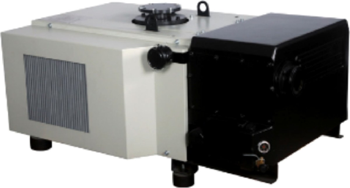
When a furnace vacuum system underperforms, the pump is rarely the cause. The duty was usually not defined. The same 630 m³/h pump is enough on a freshly baked-out hardening furnace and not enough on one whose insulation has absorbed moisture and whose load carries oil residue. The difference is the gas load, not the pump.
This note follows the order a real project runs in: the duty checklist first, then the sizing arithmetic, then the pump combinations, then the pitfalls that keep recurring.
Roughing and outgassing are two different jobs. Pumping from atmosphere down to working pressure is mostly the air inside the chamber, and it goes quickly. What takes the time is the gas that keeps coming off the hot zone, the insulation, the fixture and the load as the pressure approaches the working point, plus the small leaks at flanges, sight glasses and electrode feedthroughs. The volume leg scales with pumping speed almost linearly; the outgassing leg depends on the effective speed at the working pressure and on how low the pump can actually go. A larger pump cannot fix a pump whose ultimate pressure is above the target.
Mechanical pumps cover the stretch from atmosphere to 0.1 mbar, and to the 10⁻⁴ mbar range in two-stage models. Below that, a high-vacuum pump takes over and the mechanical pump becomes its backing pump.
The duty checklist. Twelve items decide the configuration:
| # | Item | Why it matters |
|---|---|---|
| 1 | Net chamber volume, fixture volume deducted | Sets the volume-leg pump-down time |
| 2 | Load weight and fixture surface area | The dominant gas source in the outgassing leg |
| 3 | Insulation material and thickness, date of last bake-out | Refractory fibre that has absorbed moisture multiplies the gas load |
| 4 | Working pressure and permitted fluctuation | Chooses single-stage or two-stage, and whether a Roots stage is needed |
| 5 | Cycle time from door close to heat-up | Sets the upper bound on speed — enough to hold the cycle, not the largest available |
| 6 | Quench oil, grease or organic residue inside the furnace | Decides gas ballast and whether a cold trap is needed |
| 7 | Process gas, and whether N₂, Ar or H₂ is backfilled | Compression and exhaust requirements differ by gas |
| 8 | Continuous pumping or one cycle per batch, cycles per day | Continuous duty brings oil temperature and heat dissipation into play |
| 9 | Supply: voltage, phases, frequency | Some models are not suited to 60 Hz areas; confirm before ordering |
| 10 | Exhaust route: indoors, outdoors, manifolded | Exhaust back pressure directly costs ultimate pressure |
| 11 | Footprint, door opening, floor loading | A 660 kg machine needs a foundation sized for it |
| 12 | Whether several furnaces share one vacuum source | Sharing requires a simultaneity factor and a buffer vessel |
Items 3, 6 and 10 are the ones most often skipped, and the ones that come back as commissioning problems.
Sizing: the volume term is only a floor. For the volume leg, use the isothermal estimate t = (V / S) × ln(p₁ / p₂), with V the net chamber volume, S the nominal pumping speed in m³/s, p₁ at 1013 mbar and p₂ the target. The answers come out short:
| Net chamber volume | Main pump | Nominal speed | Ideal time, 1013 → 0.5 mbar |
|---|---|---|---|
| 1.5 m³ | V0302 | 300 m³/h | about 2.3 min |
| 2.5 m³ | V0630B | 630 m³/h | about 1.8 min |
| 5 m³ | V0630B | 630 m³/h | about 3.6 min |
| 10 m³ | V0630B | 630 m³/h | about 7.3 min |
| 10 m³ | V0630B + LC1200 | 1200 m³/h nominal at the Roots stage | about 3.8 min |
Under ten minutes on paper, half an hour on the floor. The gap is outgassing and leakage, so treat the table as a floor: it tells you how far a smaller pump would drag the cycle, not what the cycle will be.
Measure the outgassing instead, with a rate-of-rise test. Pump to near the working pressure, close the main valve and record the pressure; wait five minutes and record the rise Δp. The combined gas load is Q = V × Δp / Δt in mbar·m³/s, and the effective speed needed at working pressure p is S = Q / p.
Worked case: a 2 m³ hardening furnace rises from 0.5 to 5.5 mbar in five minutes with the valve closed, so Δp is 5 mbar and Q = 2 × 5 / 300 ≈ 0.033 mbar·m³/s. Holding 0.5 mbar against that load needs S = 0.033 / 0.5 ≈ 0.067 m³/s, or 240 m³/h.
That is effective speed, not nameplate. Piping, bends, valves and filters all take their share; a piping factor around 0.7 is common, which pushes the nameplate requirement to roughly 340 m³/h. At that point the V0302 at 300 m³/h sits on the edge and the V0630B has the margin.
A new furnace, or one that has stood idle, takes visibly longer on the first pump-down because the insulation has absorbed moisture. Bake it out before blaming the pump; the rate-of-rise figure will fall on its own.
Pump combinations.
| Furnace type | Net volume | Working pressure | Configuration | Notes |
|---|---|---|---|---|
| Laboratory box or tube furnace | 0.3–0.8 m³ | Around 1 mbar | V0155 (150/175 m³/h, 4.0 kW, 0.3 mbar, G2") | Single pump, inlet filter; 388 mm wide body fits beside a bench |
| Medium tempering or annealing furnace | 1–2 m³ | 0.5 mbar | V0302 (300 m³/h, 7.5 kW, 0.5 mbar) | Little headroom; size the piping for the full G2" port |
| Medium furnace at 0.1 mbar class | 1–2 m³ | 0.1 mbar | V300B (280 m³/h, 5.5 kW, 0.08 mbar, 1100 mm body) | Short body suits installation inside a packaged unit |
| Large hardening furnace | 3–6 m³ | 0.5 mbar | V0630B (630 m³/h, 15 kW, 0.1 mbar, DN100) | Three ballast settings 0.1 / 0.8 / 2 mbar; 660 kg needs a proper foundation |
| Large furnace, deep roughing | 5–10 m³ | Below 0.05 mbar | 2V80 (74 m³/h, 3 kW, 4×10⁻⁴ mbar) + LC250, or 2V275 (255 m³/h, 7.5 kW, 5×10⁻⁴ mbar) + LC500 | 0.1 mbar is the floor for a single-stage pump; below it you need two stages; the 2V275 needs cooling water |
| Several furnaces on one source | — | Combined | Central system: V0630B or 2V275 as main pump + receiver + duty/standby | Work out the simultaneity factor before fixing pump count and vessel size |
Two things in that table get overlooked. The V0630B’s three ballast settings are functional, not decorative: closed ballast gives 0.1 mbar, single ballast 0.8 mbar and double ballast 2 mbar. A furnace drawing moisture or quench-oil vapour needs ballast to protect the oil, but with ballast open the pump will not hold below 0.5 mbar. If the process needs both low pressure and wet gas, put a condenser and water separator ahead of the pump instead of leaving the ballast open. And the 2V275 and V0630B differ by a factor of about two in speed but by three orders of magnitude in ultimate pressure — pick by target pressure, not by speed.
When a Roots stage earns its place. A Roots stage multiplies the speed available at a given pressure point; it does not change the system’s ultimate pressure, which is set by the backing pump. The order of decisions is: fix the backing pump so its ultimate sits below the target with margin; check whether the speed at the working point is enough; only then add Roots. The typical pairings published on our product pages are 2V80 + LC250 (about 3.4:1), 2V275 + LC2600, V0630B + LC1200 (about 1.9:1) and V0630B + LC2600 (about 4.1:1). The larger the ratio, the more speed can be multiplied, and the more the backing pump has to deliver at that pressure. Control-wise, interlock on pressure: bring the system down to the Roots inlet limit before starting it, because starting against a large differential overloads the motor.
One more caution: a Roots pump approaches its nominal speed only once the inlet pressure is low enough. At 0.5 mbar, the real speed leans heavily on the backing pump, so timings calculated from nominal Roots figures are optimistic.
Eight pitfalls that keep coming back.
- Using the volume formula as the cycle time. Ten cubic metres to 0.5 mbar is about seven minutes ideally and often over thirty in practice. Measure Q first.
- Expecting Roots to deepen the vacuum. It cannot. A backing pump at 0.1 mbar stays at 0.1 mbar even with a 4200 m³/h booster behind it.
- Leaving the ballast open on wet gas. On the V0630B that puts the floor at 0.8 mbar with single ballast and 2 mbar with double; a 0.5 mbar process will not hold. Remove the condensable load ahead of the pump.
- Pumping hot gas straight into the pump. Oil temperature climbs, the oil degrades faster and seal life shortens. Our product pages state 0–35 °C ambient for continuous duty; inlet temperature needs the same discipline.
- No pre-treatment for graphite dust or oxide powder. Dust wears the vanes and the cylinder wall. Fit an inlet filter, add a cyclone where the loading is heavy, and count the filter’s pressure loss against effective speed.
- Forcing reducers onto the ports. V0025A is G3/4", V0040A through V0302 are G2", V0630B is DN100 and LC1200 is ISO160. Reducers and long runs cost real speed during roughing.
- Thin, long exhaust lines. Exhaust ports are smaller than inlets (DN100 in, ISO100 out on the LC1200), and back pressure costs ultimate. Size the line and the oil-mist separator for the actual exhaust flow.
- Ordering 50 Hz figures for a 60 Hz site. Speed changes with rotational speed, and some models are not suited to 60 Hz areas — confirm before ordering.
In one line. Establish the twelve duty items, measure the gas load with a rate-of-rise test, derive effective speed from S = Q / p, divide by the piping factor to get the nameplate requirement, then choose single-stage or two-stage by target pressure and add Roots only if the speed at the working point falls short. The pump size is calculated, not compared.
Some models are not suitable for 60 Hz areas. For export projects, please confirm supply and model compatibility with us before ordering.
Related reading
- Is 0.1 mbar enough for coating backing pumps
- When to open the gas ballast, and for how long
- 2V80 versus V0100: is 4×10⁻⁴ mbar worth paying for?
- V0025A - V0100 Single-stage Oil-sealed Rotary Vane Vacuum Pump
- V0155 Single-stage Oil-sealed Rotary Vane Vacuum Pump
- V0630B Single-stage Oil-sealed Rotary Vane Vacuum Pump