
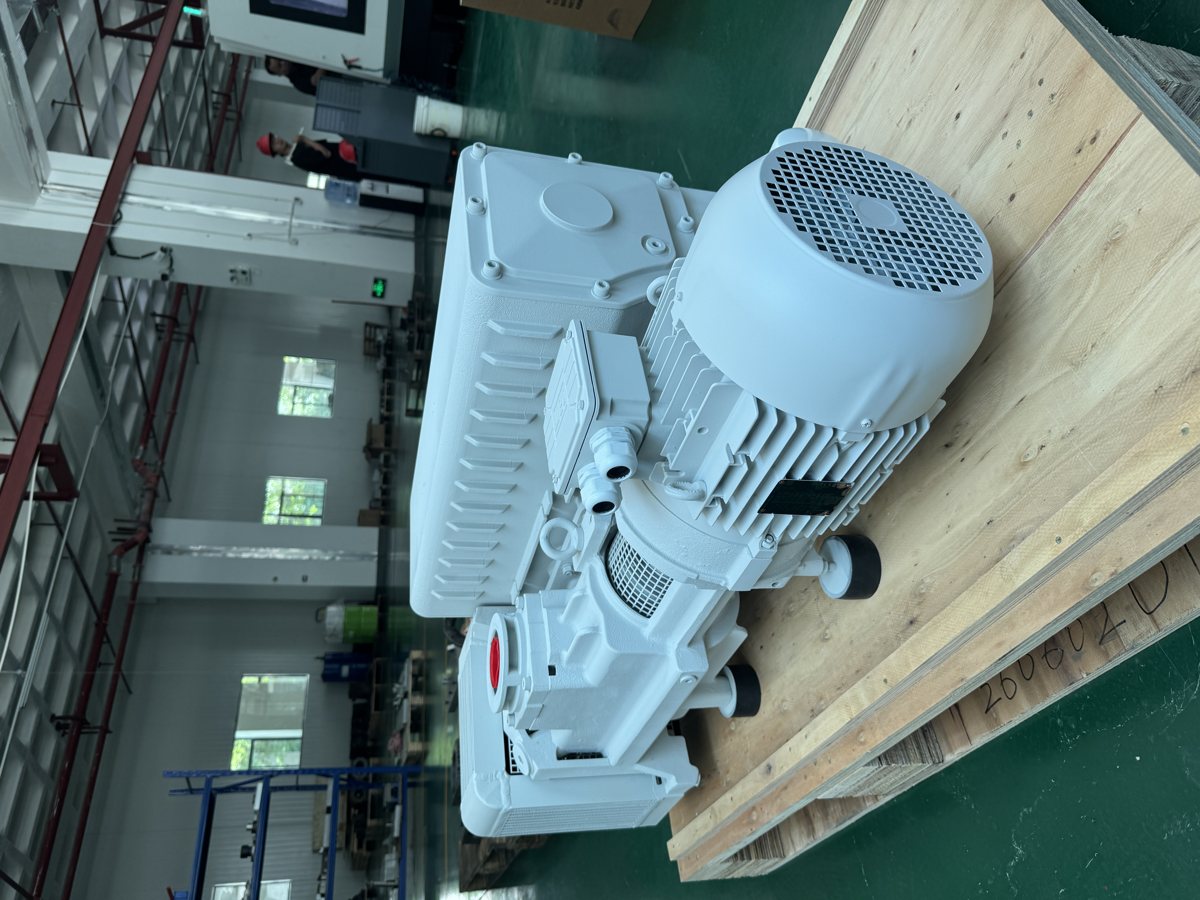
A vacuum pump acceptance test often shrinks into “read the gauge once and sign”. Then the second pump goes in and the process is still unstable. What a site acceptance has to deliver is three numbers: the ultimate pressure the chamber reaches, the pressure rise rate after isolation (converted to a leak rate), and the time from atmospheric pressure to the working pressure. Each has its own method and its own traps — gas ballast state, gauge range, whether the fixture basket was dried. Below is one walk-through on a 2 m³ vacuum heat treatment furnace with a DPL-V300B, with every formula and substitution written out.
1. Ultimate pressure: settle three conditions before reading
First, the gas ballast state. DPL-V300B holds ≤8×10⁻² mbar with the ballast closed and ≤0.7 mbar with it open; the V0040A to V0100 range goes from 0.1 mbar to 0.5 mbar. Measuring ultimate pressure with the ballast open does not measure the pump — it measures the dry air the ballast admits. A record that omits the ballast state cannot be compared with anything.
Second, stability. A reading taken while pressure is still falling means nothing. The working rule is three readings 30 minutes apart with less than 5% spread. On a 2 m³ chamber with a V300B, cold and empty, the stable point arrives in 60 to 90 minutes and lands near 0.09 mbar, consistent with the ≤8×10⁻² mbar catalogue value.
Third, the gauge and the tapping point. Below 0.1 mbar a Pirani reading depends on gas species — air and argon do not read the same. For 10⁻³ mbar work, use a capacitance diaphragm or a combined gauge. State where the pressure is measured: at the pump port you measure the pump, at the chamber you measure the system, and between them sit piping and valves. ISO 21360-1:2020 measures base pressure on a standard test dome, which is not the same quantity as a chamber reading on site. Comparing a catalogue figure with a chamber gauge directly is where most disagreements start.
2. Pressure rise rate: one number, two units
Isolate the chamber at ultimate pressure by closing the pump set and the main valve, then record pressure against time. Following T/CSEA 36-2025, clause 5.3.2: record for no less than 12 hours, take two points on the linear section at least 300 seconds apart, and normalise pressure by absolute temperature so that ambient drift does not masquerade as a leak.
Worked example: 2 m³ furnace chamber, isolated at p₁ = 0.12 mbar at t₁ = 0, reaching p₂ = 0.35 mbar at t₂ = 4 h (14,400 s).
- Rise Δp = 0.35 − 0.12 = 0.23 mbar = 23 Pa
- Rise rate = 23 Pa ÷ 4 h = 5.75 Pa/h
- Leak rate Q = V·Δp/Δt = 2 m³ × 23 Pa ÷ 14,400 s = 0.0032 Pa·m³/s
With the temperature going from 295 K to 297 K, normalising by p/T gives a rise of 0.229 mbar and a rate of 5.73 Pa/h — 1% away from the uncorrected figure. A drift within ±3 K can be ignored; beyond that it must be corrected, or the “leak” may be nothing but a warm room.
Two criteria apply. GB/T 22561—2008, clause 5.1.6, requires the pressure rise rate of a cold, empty, thoroughly dried furnace to stay below 0.67 Pa/h; Annex A of the same standard lists allowable rates for the working state by material — 1.33 Pa/h for titanium and its alloys, 2.66 Pa/h for nickel and cobalt alloys, 6.65 Pa/h for structural and tool steels. At 5.75 Pa/h the measured value is 8.5 times the cold empty limit.
Exceeding the limit does not prove a leaking vessel. Outgassing and virtual leaks also push pressure up, but they decay and their curves bend; only a real leak contributes a straight line. So the next step is a staged re-test: close the valve to the fixture basket and pump the vessel alone. That gives 0.45 Pa/h — below 0.67, so the vessel passes, and the extra 5.3 Pa/h belongs to the undried basket. After baking the basket at 200 °C for two hours, the rate returns below 0.6 Pa/h.
3. Turning a leak rate into “how low can it go”
A leak rate by itself is not a verdict; the verdict is the pressure it limits. At steady state p = Q / S_eff, with Q in mbar·L/s and S in L/s. Unit note first: 1 Pa·m³/s = 10 mbar·L/s, so the 0.0032 Pa·m³/s above is 0.032 mbar·L/s.
DPL-V300B is rated 280 m³/h nominal and 240 m³/h measured, i.e. 66.7 L/s; with a 0.7 allowance for piping and valves the effective speed is 46.7 L/s. The leak-limited pressure is therefore:
p = 0.032 ÷ 46.7 = 6.9×10⁻⁴ mbar
That is far below the 0.09 mbar actually read on site, which tells us the 0.09 mbar is set by the pump’s own ultimate pressure and the gauge, not by the leak. This check is worth doing every time: when the reading disagrees with the catalogue, calculate whether the limit comes from leak rate or from pump type before touching a flange.
Run the same relation backwards and you get an acceptance table (effective speed held at 46.7 L/s):
| Target working pressure | Allowed leak rate Q = S·p | Margin over 0.032 mbar·L/s |
|---|---|---|
| 1×10⁻² mbar | 0.47 mbar·L/s | about 15×, fine |
| 1×10⁻³ mbar | 0.047 mbar·L/s | about 1.5×, thin |
| 1×10⁻⁴ mbar | 0.0047 mbar·L/s | not enough |
The last row is not a call for more leak hunting, it is a wrong pump type. The single-stage V300B holds ≤8×10⁻² mbar; 1×10⁻⁴ mbar is out of its range. That level needs a two-stage pump — the 2V80 reaches 4×10⁻⁴ mbar. See /en/products/dp-2v80-2v275/ for the data.
4. Pump-down time: back-calculate the effective speed
For the roughing stage, t = (V / S_eff) × ln(P₀/P₁). For 2,000 L from 1,013 mbar to 1 mbar the log term is 6.92:
t = 2,000 ÷ 46.7 × 6.92 = 296 s
The site measurement took 480 s. The gap is not a weak pump, it is pumping speed that never reached the chamber. Invert the relation — this is the pump-down method of ISO 21360-1:2020:
S_eff = V ÷ t × ln(P₀/P₁) = 2,000 ÷ 480 × 6.92 = 28.8 L/s
28.8 L/s is 104 m³/h, only 43% of the 240 m³/h measured at the pump. Check three things in order: whether the valve bore is smaller than the pump port (the V300B has a G2″ flange; use DN50 or larger), whether the inlet line runs through flexible hose and several elbows, and whether the inlet filter is already loaded. The sizing method sits in /en/news/piping-and-valves/, and /en/calculator/ recomputes the pump-down time once the pipe bore is fixed.
The second stage, 1 mbar to 0.1 mbar, has ln(1/0.1) = 2.30, i.e. 160 s at the measured 28.8 L/s, for about 640 s total, roughly 10.7 minutes. Real furnaces take longer: below 1 mbar the volume flow rate falls with pressure, and process curves are normally given 30% to 50% margin over measurement.
5. What the acceptance record must contain
| Item | Required entries |
|---|---|
| Duty | Ambient temperature, gas ballast open/closed, gas species, voltage and frequency (50 or 60 Hz) |
| Ultimate pressure | Gauge model and range, tapping point, stability criterion (three readings within 30 min) |
| Rise rate | Isolation moment, 12-hour curve, the two linear-section points and their interval, temperature normalisation, standard clause referenced |
| Pump-down time | Start and end pressure, measured seconds, back-calculated effective speed, percentage of nominal |
Frequency deserves its own line: the same pump has different speeds at 50 Hz and 60 Hz — V0025A is 20/26 m³/h, V0155 is 150/175 m³/h. The specification notes that some models are not suited to 60 Hz regions; confirm motor and speed configuration with the factory before acceptance on an export project. The 60 Hz calculation is covered in /en/news/running-60-hz-pumping-speed-motor-power-voltage/, and the industry requirements in /en/industries/heat-treatment/.