
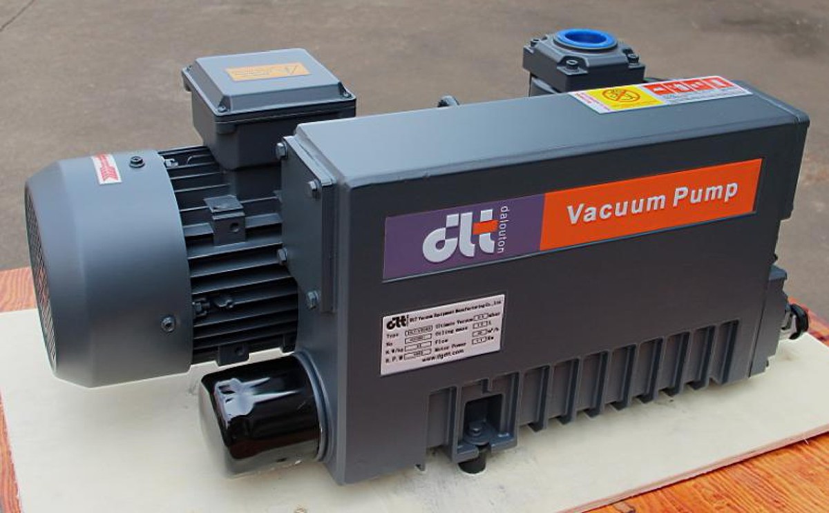
Pick-and-place on an electronics line looks simple: the cup touches the part, the pump evacuates, the arm moves, the valve releases. Undersize the pump and parts drop mid-transfer; oversize it and you pay for capacity and noise you never use. Here is where the boundary sits, by speed and cup size.
Force first, speed second. Holding force is pressure difference times area. Take a 50 mm cup and a pump pulling to -60 kPa (about 40 kPa absolute): area = π × 25² ≈ 1963 mm² = 0.00196 m², so theoretical force ≈ 60 kPa × 0.00196 m² ≈ 118 N. With a factor of two for safety, that is roughly 59 N, or a flat 6 kg part. Porous parts (paper, foam, fabric) or rough surfaces cut this in half again.
Where each oil-free model fits.
| Model | Speed (50/60 Hz) | Power | Port | Typical use |
|---|---|---|---|---|
| V8 | 6.8 / 8.6 m³/h | 0.28 kW | G3/8" | single cup, small parts, piping under 1 m |
| V10 | 10 / 12 m³/h | 0.4 kW | G1/2" | two cups, small station with a buffer tank |
| V16 | 16 / 18.2 m³/h | 0.55 kW | G1/2" | three to six points, 2–3 m of piping |
| V25/40 | 40 / 45 m³/h | 1.3 kW | G3/4" | large panels, many points at once, long runs |
V3 (3.4 / 4.2 m³/h, 0.18 kW, 90 kPa ultimate) suits laboratory work or very small chambers; it is not the pick for a line running continuous cycles.
Estimating evacuation time. For a volume V pulled from atmosphere to p, a rough estimate is t = (V / S) × ln(1013 / p), with S converted to litres per second. A 0.5 L cup-and-pipe volume on a V10 (10 m³/h ≈ 2.78 L/s) to -60 kPa gives t ≈ (0.5 / 2.78) × ln(1013 / 40) ≈ 0.58 s. That figure covers the pump alone, not valve response or line losses. For cycles under 0.5 s, keep the run short, the bore wide, and put the buffer tank near the cup.
When V16 is no longer enough. Step up to V25/40 or a central system when: more than six points must hold simultaneously; the part leaks more than 30% of pump capacity; the run exceeds 3 m with several bends; or dust and coolant mist force a pre-filter whose pressure drop eats the margin. Leakage is the deciding number — measure it with the cup open and compare against the nameplate speed.
Why oil-free. Electronics work cannot tolerate oil mist on parts or in clean areas, and an oil-free rotary vane pump exhausts no oil; the vanes lubricate the chamber themselves. The trade-off is ultimate pressure: most oil-free models sit around 90 kPa, so duties below 0.1 mbar call for an oil-sealed pump or a Roots set.
To size one, send us part size and weight, cup count and diameter, pipe length and bore, cycle time, dust or coolant exposure, and whether the supply is single or three phase.
Related reading
- Where oil-free rotary vane vacuum pumps fit
- Routine care for oil-free rotary vane vacuum pumps
- Inside a single-stage oil-free rotary vane pump
- V15/25/40H Single-stage Oil-free Rotary Vane Vacuum Pump
- V25/40 Single-stage Oil-free Rotary Vane Vacuum Pump (single suction)
- V10 Single-stage Oil-free Rotary Vane Vacuum Pump